Last updated on April 24th, 2023 at 03:11 pm
Evaporator Fan Controllers
Before we get started, please learn that what we’re going to talk about is the fan nearby the evaporator, to push cold air into the storage room. It is not the fan nearby the condenser or another blower nearby the compressor.
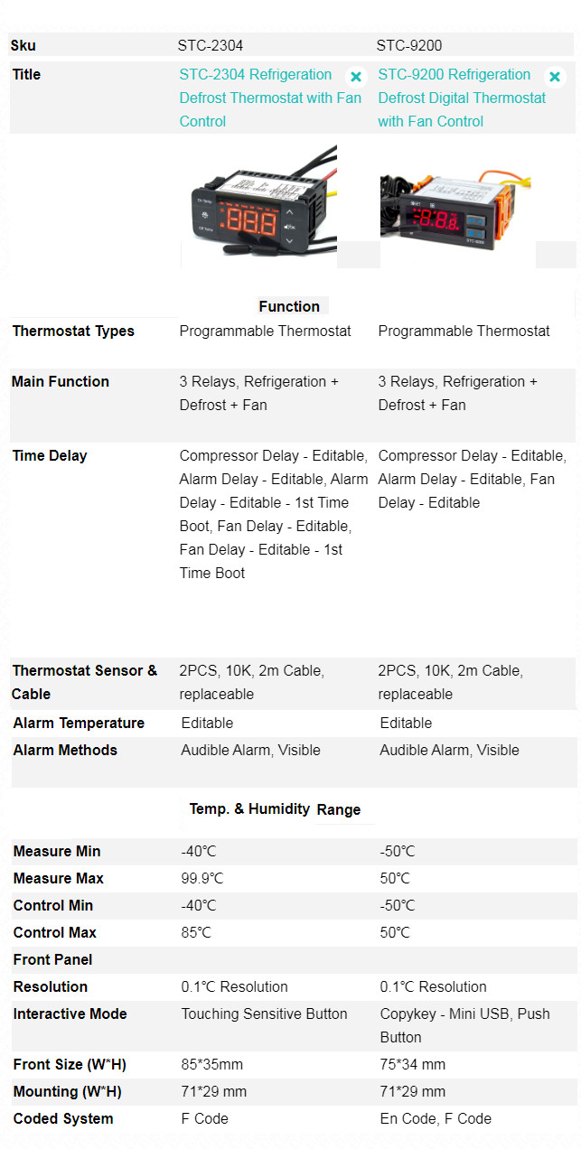
Both the STC-2304 and STC-9200 defrost thermostats offer 3 output relays for controlling refrigeration, evaporator defrosting, and evaporator Fan, then which one is the best temperature controller for a cold storage room? Which one should you take?
Differences in Specification
From the specification table of each product, you will find that
- The controllable range of STC-2304 is from -40 to 85°C, it adopts a modern touch-sensitive key, and offers more Time delay options;
- On the other hand, STC-9200 from -50 to 50 Celsius degree, uses the normal press button, but with a copy-key port on the back panel.
Function Menu & Parameters Comparison
More differences among them in detail, let’s compare it from the function menu list.
| Blocks | STC-9200 | STC-2304 | ||||
|---|---|---|---|---|---|---|
| EN Code | F Code | Function | Code | Function | ||
| Block 1 | SET | F1 | SP (Temperature Set-Point) | ON TEMP | Compressor Starts Temperature | |
| HY | F2 | Temperature Hysteresis | OFF TEMP | Compressor Stops Temperature | ||
| US | F3 | Upper limit of SP could reach | ||||
| LS | F4 | Lower limit of SP could reach | ||||
| Block 2 | AC | F5 | Compressor Delay Time | F9 | Compressor Delay Time | |
| IDF | F6 | Defrost Cycle / Interval Time | F2 | Defrost Cycle / Interval Time | ||
| MDF | F7 | Defrost Lasting Time | F1 | Defrost Lasting Time | ||
| DTE | F8 | Defrost Stop Temperature | F6 | Defrost Stop Temperature | ||
| Block 3 | FDT | F9 | Water dripping Time after Defrost | F4 | Water dripping Time after Defrost | |
| F8 | Time delay for fan 1st time running after pass F4 | |||||
| Block 4 | TDF | F10 | Defrosting by EL: Electrical-heating, HTG: Hot Gas | F5 | Defrosting by, 0 = Electric-Thermal, 1 = Hot Air, 2 = Natural Wind |
|
| Block 5 | DCT | F11 | Count mode of defrost cycle: RT: Cumulative time from controller power on; COH: Cumulative time of the compressor working. | F3 | Count mode of defrost cycle: 0: Cumulative time from controller power on; 1: Cumulative time of compressor working. |
|
| Block 6 | DFD | F12 | Display mode when defrosting: RT: Show Room sensor temperature; IT: show defrost sensor temperature (lasting 10m after defrosting over) | |||
| Block 7 | FNC | F13 | evaporator Fan output options: CRT: Fan Starts by F14/FOT, Stop by F16/FST; O-N: continuous operation except defrosting begin; C-N: Fan start-up later than the compressor (FOD/F15), Stop if defrost begins. | |||
| FOT | F14 | Defrost sensor Temperature for Fan Starts | ||||
| FOD | F15 | Time delay seconds for evaporation Fan: FOD < 0 Fan start-up earlier than the compressor (FOD/F15) seconds; FOD/F15 ≥0, controller by F13/FNC. | F7 | evaporation Fan modes: <0, earlier than the compressor start; =0, synchronous with the compressor; >0, later than the compressor starts; C: continuous working without interval; D: continuous working except defrosting time. |
||
| FST | F16 | Defrost sensor Temperature for Fan Stops | ||||
| Block 8 | ALU | F17 | Room Sensor Temperature to Trigger Alarm (Not the "Over-Temperature" value) | Upper Limit | F11 | Room sensor Over-Temperature Value to Trigger Alarm |
| ALL | F18 | Lower Limit | ||||
| ALD | F19 | Time delay | F10 | Room Temp. Alarm Delay Time for first time power on | ||
| F12 | Room Temp. Alarm Delay Time after time pass F10 | |||||
| Block 9 | OT | F20 | Calibration = Real - Measured Temperature | F13 | Calibration = Real - Measured Temperature | |
As you see, there are 8 blocks:
Block 1, Set the Controlling Temperature Range
| Blocks | STC-9200 | STC-2304 | ||||
|---|---|---|---|---|---|---|
| EN Code | F Code | Function | Code | Function | ||
| Block 1 | SET | F1 | SP (Temperature Set-Point) | ON TEMP | the compressor Starts Temperature | |
| HY | F2 | Temperature Hysteresis | OFF TEMP | the compressor Stops Temperature | ||
| US | F3 | Upper limit of SP could reach | N/A | N/A | ||
| LS | F4 | Lower limit of SP could reach | N/A | N/A | ||
- STC-2304 is a high-low-limit temperature controller which means the suitable temperature range is determined by an upper limit (on temp) and a lower limit (off temp);
- STC-9200 utilizes the temperature set-point and Temperature Hysteresis value to carry out the same purpose;
Block 2, Compressor delay time and the defrosting timing setting.
| Blocks | STC-9200 | STC-2304 | ||||
|---|---|---|---|---|---|---|
| EN Code | F Code | Function | Code | Function | ||
| Block 2 | AC | F5 | the compressor Delay Time | F9 | the compressor Delay Time | |
| IDF | F6 | Defrost Cycle / Interval Time | F2 | Defrost Cycle / Interval Time | ||
| MDF | F7 | Defrost Lasting Time | F1 | Defrost Lasting Time | ||
| DTE | F8 | Defrost Stop Temperature | F6 | Defrost Stop Temperature | ||
totally the same, no more words here.
Block 3, Water Dripping Time After Thawing
| Blocks | STC-9200 | STC-2304 | ||||
|---|---|---|---|---|---|---|
| EN Code | F Code | Function | Code | Function | ||
| Block 3 | FDT | F9 | Water dripping Time after Defrost | F4 | Water dripping Time after Defrost | |
| N/A | N/A | N/A | N/A | F8 | Time delay for evaporator fan 1st time running after pass F4 | |
- STC-2304 exist two parameters related to Room Temp. Alarm Delay Time, F10 is for the first time power on, and F12 is for the rest of the time after F10 overs.
- STC-9200 just owns one delay time F19, you can press any key to stop the annoying screaming, however, the display still shows an error code before the air temperature colds down.
Block 4, Defrosting Methods
| Blocks | STC-9200 | STC-2304 | ||||
|---|---|---|---|---|---|---|
| EN Code | F Code | Function | Code | Function | ||
| Block 4 | TDF | F10 | Defrosting by EL: Electrical-heating, HTG: Hot Gas | F5 | Defrosting by, 0 = Electric-Thermal, 1 = Hot Air, 2 = Natural Wind |
|
- Both of them offer electrical heating and thermal gas from the compressor reversal rolling.
- STC-2304 exist one more option, which is defrosting by the wind from the fan, it is a kind of internal recycling.
Block 5 Timing mode of defrost cycle
| Blocks | STC-9200 | STC-2304 | ||||
|---|---|---|---|---|---|---|
| EN Code | F Code | Function | Code | Function | ||
| Block 5 | DCT | F11 | Count mode of defrost cycle: RT: Cumulative time from controller power on; COH: Cumulative time of the compressor working. | F3 | Count mode of defrost cycle: 0: Cumulative time from controller power on; 1: Cumulative time of the compressor working. |
|
Both of them offer two methods for counting time, and they are the same.
Block 6, What is the temperature Value on the Screen?
| Blocks | STC-9200 | STC-2304 | ||||
|---|---|---|---|---|---|---|
| EN Code | F Code | Function | Code | Function | ||
| Block 6 | DFD | F12 | Display mode when defrosting: RT: Show Room sensor temperature; IT: show defrost sensor temperature (lasting 10m after defrosting over) | N/A | N/A | |
STC-9200 allows shows the evaporator temperature instead of the storage room temperature by setting the DFD/F12.
STC-2304 Without this function, the user must hold the “UP” Key for 3s to check the defrost temp after unlocking the keys.
Block 7, Fan Working Mode and Time
| Blocks | STC-9200 | STC-2304 | ||||
|---|---|---|---|---|---|---|
| EN Code | F Code | Function | Code | Function | ||
| Block 7 | FNC | F13 | evaporator Fan output options: CRT: Fan Starts by F14/FOT, Stop by F16/FST; O-N: continuous operation except defrosting begin; C-N: Fan start-up later than the compressor (FOD/F15), Stop if defrost begins. | N/A | N/A | |
| FOT | F14 | Defrost sensor Temperature for Fan Starts | N/A | N/A | ||
| FOD | F15 | Time delay seconds for evaporation Fan: FOD < 0 Fan start-up earlier than the compressor (FOD/F15) seconds; FOD/F15 ≥0, controller by F13/FNC. | F7 | evaporation Fan modes: <0, earlier than the compressor start; =0, synchronous with the compressor; >0, later than the compressor starts; C: continuous working without interval; D: continuous working except defrosting time. |
||
| FST | F16 | Defrost sensor Temperature for Fan Stops | N/A | N/A | ||
From the above part,
- STC-9200 starts and stops the refrigerator evaporator fan by the time or the defrost sensor temperature (F14, F16), with it the freezer fan will not always run, just working when necessary;
- STC-2304 just can control the evaporator fan by time, without the temperature condition.
When does the evaporator fan turn on or off?
This simple question with a complicated answer, because each of the above evaporator fan controllers offers multi-plans for the fan.
- If you want the evaporator fan is always run, only the SCT-2304 is ok, because when the F7 = C, the fan will ignore the defrost status.
- But if you like the fan to stop working during the defrosting time, both of them are ok.
- we’ve marked the same function with the same color in the above comparison table, we believe you could understand it easily.
How to set the Defrost termination/fan delay?
After the defrost is over, assume the instant time has passed the compressor delay time, and the refrigerator starts
- STC-9200,
- firstly, Set the fan delay time in FOD/F15 ( should > 0, assume it is 5min)
- Next set the F13 = C-N, the fan will delay 5 mins before startup.
- STC-2304,
- Just set the F7 = 1 or a larger number, and you’ve finished the configuration.
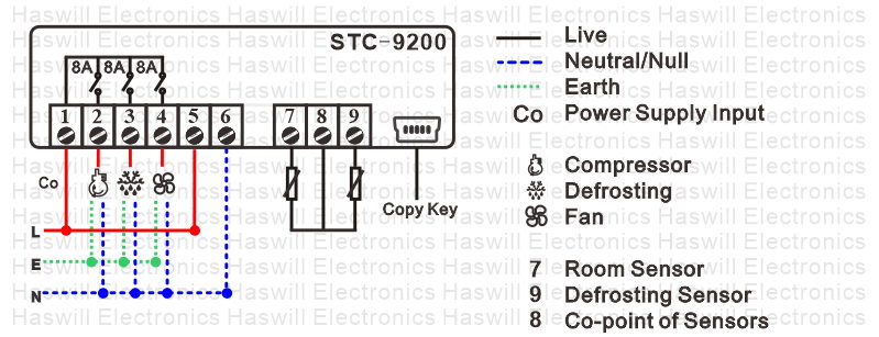
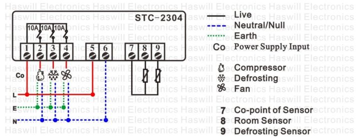
There is no strange method in the wiring diagram of these defrost fan controllers, the key is to understand the menu list and manual.
Block 8, Alarm Room Temperature
| Blocks | STC-9200 | STC-2304 | ||||
|---|---|---|---|---|---|---|
| EN Code | F Code | Function | Code | Function | ||
| Block 8 | ALU | F17 | Room Sensor Temp. (Not Over-Temp.) to Trigger Alarm | Upper Limit | F11 | Room sensor Over-Temperature Value to Trigger Alarm |
| ALL | F18 | Lower Limit | N/A | N/A | ||
| ALD | F19 | Time delay | F10 | Room Temp. Alarm Delay Time for 1st time power on | ||
| N/A | N/A | N/A | N/A | F12 | Room Temp. Alarm Delay Time after time pass F10 | |
both of them could trigger the alarming function once the temperature exceeds the safe range, but there is a little difference:
- STC-9200 offers separate “low limit and high limit temperature values” to define alarm points, the advantage is these two values could be different and need not to plus or minus other data.
- STC-2304 just supplies one Over-Temperature value to set the silence range out which will trigger alarming, the micro-computer inside will calculate the upper limit ( the OnTemp Value + the Over Temp Value), and the lower limit ( The Off Temp Value – the Over Temp Value); yet, it offers a sweety option namely “Room Temp. Alarm Delay Time” for 1st-time boot.
The Difference Part in Wiring Diagram
Conclusion
The max current is different;
Both of them support forced defrosting manually;
Both of them alarm through the error code on display and buzzer screams, but without alarm output like STC-9100;
Lorem ipsum dolor sit amet, consectetur adipiscing elit. Ut elit tellus, luctus nec ullamcorper mattis, pulvinar dapibus leo.
STC-9200 Evaporator Defrost & Fan Controller Features
- It offers a wider controllable range, owns press-type buttons;
- could show the defrosting sensor temperature instead of room temperature on the display;
- Regulates the evaporative cooling fan by time and temperature;
- separately user menu and admin menu;
- With a Mini-SUB port on the back panel, Batch upload configuration data by USB-Disk is achievable, saving time if you have a lot of walk-in cold storage rooms.
STC-2304 Evaporator Defrost & Fan Controller Features
- The STC-2304 fan regulating thermostat control from -50°C ~ 50°C;
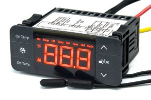
- owns touch-sensitive keys;
- offers friendly options of time delay for the 1st-time power on;
- controls the evaporator fan only by time;
- shortcut key to set the suitable temperature range, and auto-lock the keys to prevent mistakenly touching them.


